
下载
2013 Microchip Technology Inc. DS40001683B-page 1
PIC16(L)F170X
This document includes the
programming specifications for the
following devices:
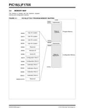
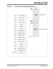
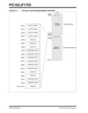
1.0 OVERVIEW
The device can be programmed using either the high-
voltage In-Circuit Serial Programming™ (ICSP™)
method or the low-voltage ICSP method.
1.1 Hardware Requirements
1.1.1 HIGH-VOLTAGE ICSP
PROGRAMMING
In High-Voltage ICSP mode, the device requires two
programmable power supplies: one for V
DD and one for
the MCLR
/VPP pin.
1.1.2 LOW-VOLTAGE ICSP
PROGRAMMING
In Low-Voltage ICSP mode, the PIC16(L)F170X
devices can be programmed using a single V
DD source
in the operating range. The MCLR
/VPP pin does not
have to be brought to a different voltage, but can
instead be left at the normal operating voltage.
1.1.2.1 Single-Supply ICSP Programming
The LVP bit in Configuration Word 2 enables single-
supply (low-voltage) ICSP programming. The LVP bit
defaults to a ‘1’ (enabled) from the factory. The LVP bit
may only be programmed to ‘0’ by entering the High-
Voltage ICSP mode, where the MCLR
/VPP pin is raised
to V
IHH. Once the LVP bit is programmed to a ‘0’, only
the High-Voltage ICSP mode is available and only the
High-Voltage ICSP mode can be used to program the
device.
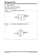
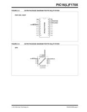
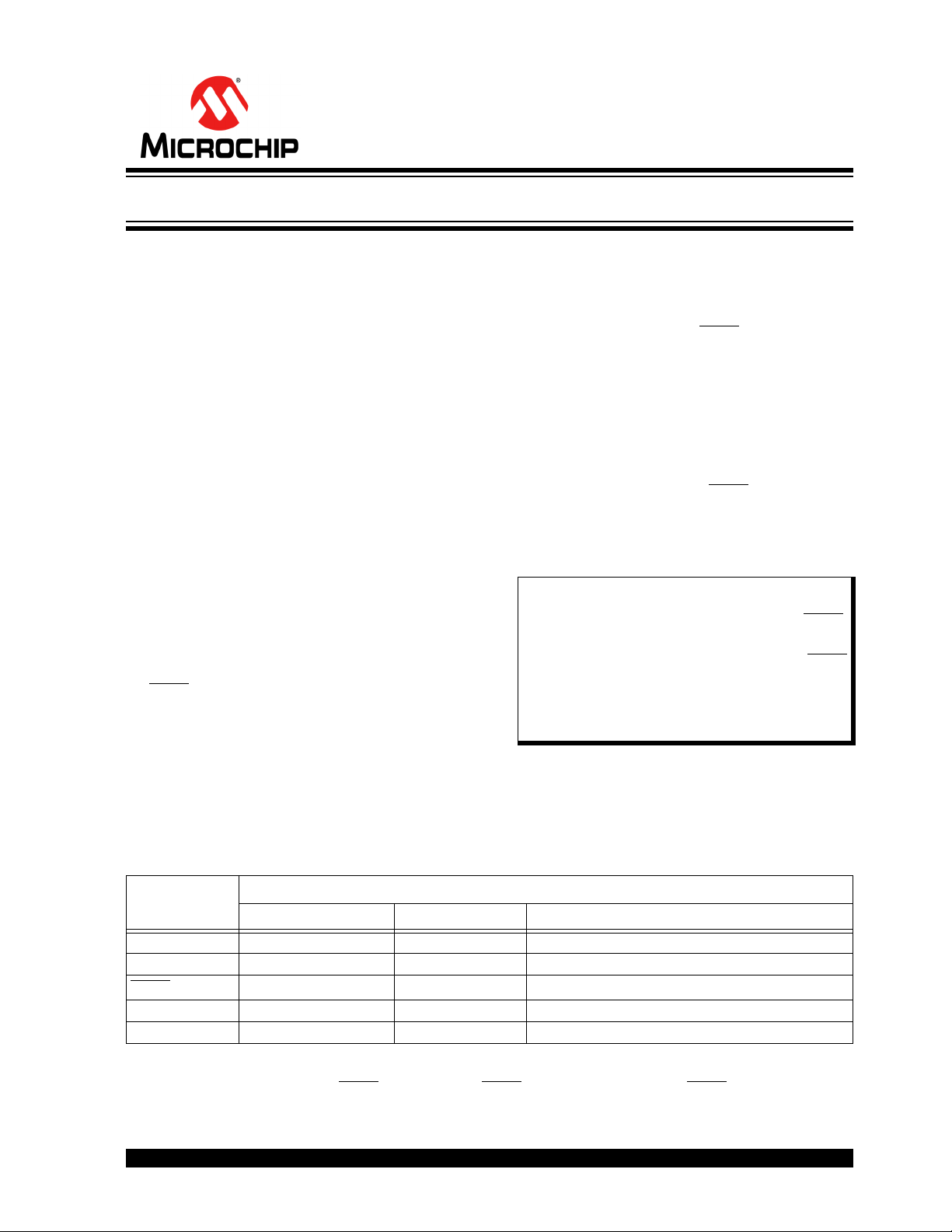
1.2 Pin Utilization
Five pins are needed for ICSP programming. The pins
are listed in Ta ble 1 -1.
• PIC16F1703 • PIC16LF1703
• PIC16F1704 • PIC16LF1704
• PIC16F1705 • PIC16LF1705
• PIC16F1707 • PIC16LF1707
• PIC16F1708 • PIC16LF1708
• PIC16F1709 • PIC16LF1709
Note 1: The High-Voltage ICSP mode is always
available, regardless of the state of the
LVP bit, by applying V
IHH to the MCLR/
V
PP pin.
2: While in Low-Voltage ICSP mode, MCLR
is always enabled, regardless of the
MCLRE bit, and the port pin can no
longer be used as a general purpose
input.
TABLE 1-1: PIN DESCRIPTIONS DURING PROGRAMMING FOR PIC16(L)F170X
Pin Name
During Programming
Function Pin Type Pin Description
ICSPCLK ICSPCLK I Clock Input – Schmitt Trigger Input
ICSPDAT ICSPDAT I/O Data Input/Output – Schmitt Trigger Input
MCLR
/VPP Program/Verify mode P
(1)
Program Mode Select/Programming Power Supply
VDD VDD P Power Supply
V
SS VSS P Ground
Legend: I = Input, O = Output, P = Power
Note 1: The programming high voltage is internally generated. To activate the Program/Verify mode, high voltage
needs to be applied to MCLR input. Since the MCLR is used for a level source, MCLR does not draw any
significant current.
PIC16(L)F170X Memory Programming Specification