
下载
REV. 0
a
AN-613
APPLICATION NOTE
One Technology Way • P.O. Box 9106 • Norwood, MA 02062-9106 • Tel: 781/329-4700 • Fax: 781/326-8703 • www.analog.com
Programming the Automatic Fan Speed Control Loop
By Mary Burke
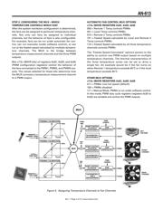
AUTOMATIC FAN SPEED CONTROL
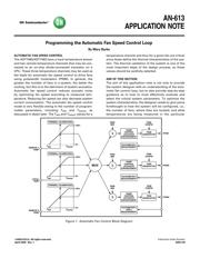
The ADT7460/ADT7463 have a local temperature sensor
and two remote temperature channels that may be con-
nected to an on-chip diode-connected transistor on a
CPU. These three temperature channels may be used as
the basis for automatic fan speed control to drive fans
using pulsewidth modulation (PWM). In general, the
greater the number of fans in a system, the better the
cooling, but this is to the detriment of system acoustics.
Automatic fan speed control reduces acoustic noise
by optimizing fan speed according to measured tem-
perature. Reducing fan speed can also decrease system
current consumption. The automatic fan speed control
mode is very flexible owing to the number of program-
mable parameters, including T
MIN
and T
RANGE
, as
discussed in detail later. The T
MIN
and T
RANGE
values for a
temperature channel and thus for a given fan are critical
since these define the thermal characteristics of the sys-
tem. The thermal validation of the system is one of the
most important steps of the design process, so these
values should be carefully selected.
AIM OF THIS SECTION
The aim of this application note is not only to provide
the system designer with an understanding of the auto-
matic fan control loop, but to also provide step-by-step
guidance as to how to most effectively evaluate and
select the critical system parameters. To optimize the
system characteristics, the designer needs to give some
forethought to how the system will be configured, i.e.,
the number of fans, where they are located, and what
temperatures are being measured in the particular
TACHOMETER 1
MEASUREMENT
RAMP
CONTROL
(ACOUSTIC
ENHANCEMENT
TACHOMETER 2
MEASUREMENT
RAMP
CONTROL
(ACOUSTIC
ENHANCEMENT
TACHOMETER 3
AND 4
MEASUREMENT
PWM
GENERATOR
PWM
CONFIG
PWM
GENERATOR
PWM
CONFIG
RAMP
CONTROL
(ACOUSTIC
ENHANCEMENT
PWM
GENERATOR
PWM
CONFIG
�
PWM
MIN
�
PWM
MIN
�
PWM
MIN
MUX
THERMAL CALIBRATION
100%
0%
T
MIN
T
RANGE
THERMAL CALIBRATION
100%
0%
T
MIN
T
RANGE
THERMAL CALIBRATION
100%
0%
T
MIN
T
RANGE
PWM1
PWM2
PWM3
REMOTE 1
TEMP
LOCAL
TEMP
REMOTE 2
TEMP
Figure 1. Automatic Fan Control Block Diagram
REV. 0
a
AN-613
APPLICATION NOTE
One Technology Way • P.O. Box 9106 • Norwood, MA 02062-9106 • Tel: 781/329-4700 • Fax: 781/326-8703 • www.analog.com
Programming the Automatic Fan Speed Control Loop
By Mary Burke
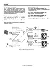
AUTOMATIC FAN SPEED CONTROL
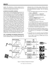
The ADT7460/ADT7463 have a local temperature sensor
and two remote temperature channels that may be con-
nected to an on-chip diode-connected transistor on a
CPU. These three temperature channels may be used as
the basis for automatic fan speed control to drive fans
using pulsewidth modulation (PWM). In general, the
greater the number of fans in a system, the better the
cooling, but this is to the detriment of system acoustics.
Automatic fan speed control reduces acoustic noise
by optimizing fan speed according to measured tem-
perature. Reducing fan speed can also decrease system
current consumption. The automatic fan speed control
mode is very flexible owing to the number of program-
mable parameters, including T
MIN
and T
RANGE
, as
discussed in detail later. The T
MIN
and T
RANGE
values for a
temperature channel and thus for a given fan are critical
since these define the thermal characteristics of the sys-
tem. The thermal validation of the system is one of the
most important steps of the design process, so these
values should be carefully selected.
AIM OF THIS SECTION
The aim of this application note is not only to provide
the system designer with an understanding of the auto-
matic fan control loop, but to also provide step-by-step
guidance as to how to most effectively evaluate and
select the critical system parameters. To optimize the
system characteristics, the designer needs to give some
forethought to how the system will be configured, i.e.,
the number of fans, where they are located, and what
temperatures are being measured in the particular
TACHOMETER 1
MEASUREMENT
RAMP
CONTROL
(ACOUSTIC
ENHANCEMENT
TACHOMETER 2
MEASUREMENT
RAMP
CONTROL
(ACOUSTIC
ENHANCEMENT
TACHOMETER 3
AND 4
MEASUREMENT
PWM
GENERATOR
PWM
CONFIG
PWM
GENERATOR
PWM
CONFIG
RAMP
CONTROL
(ACOUSTIC
ENHANCEMENT
PWM
GENERATOR
PWM
CONFIG
�
PWM
MIN
�
PWM
MIN
�
PWM
MIN
MUX
THERMAL CALIBRATION
100%
0%
T
MIN
T
RANGE
THERMAL CALIBRATION
100%
0%
T
MIN
T
RANGE
THERMAL CALIBRATION
100%
0%
T
MIN
T
RANGE
PWM1
PWM2
PWM3
REMOTE 1
TEMP
LOCAL
TEMP
REMOTE 2
TEMP
Figure 1. Automatic Fan Control Block Diagram
REV. 0
a
AN-613
APPLICATION NOTE
One Technology Way • P.O. Box 9106 • Norwood, MA 02062-9106 • Tel: 781/329-4700 • Fax: 781/326-8703 • www.analog.com
Programming the Automatic Fan Speed Control Loop
By Mary Burke
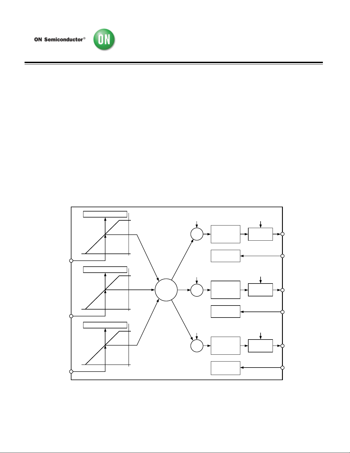
AUTOMATIC FAN SPEED CONTROL
The ADT7460/ADT7463 have a local temperature sensor
and two remote temperature channels that may be con-
nected to an on-chip diode-connected transistor on a
CPU. These three temperature channels may be used as
the basis for automatic fan speed control to drive fans
using pulsewidth modulation (PWM). In general, the
greater the number of fans in a system, the better the
cooling, but this is to the detriment of system acoustics.
Automatic fan speed control reduces acoustic noise
by optimizing fan speed according to measured tem-
perature. Reducing fan speed can also decrease system
current consumption. The automatic fan speed control
mode is very flexible owing to the number of program-
mable parameters, including T
MIN
and T
RANGE
, as
discussed in detail later. The T
MIN
and T
RANGE
values for a
temperature channel and thus for a given fan are critical
since these define the thermal characteristics of the sys-
tem. The thermal validation of the system is one of the
most important steps of the design process, so these
values should be carefully selected.
AIM OF THIS SECTION
The aim of this application note is not only to provide
the system designer with an understanding of the auto-
matic fan control loop, but to also provide step-by-step
guidance as to how to most effectively evaluate and
select the critical system parameters. To optimize the
system characteristics, the designer needs to give some
forethought to how the system will be configured, i.e.,
the number of fans, where they are located, and what
temperatures are being measured in the particular
TACHOMETER 1
MEASUREMENT
RAMP
CONTROL
(ACOUSTIC
ENHANCEMENT
TACHOMETER 2
MEASUREMENT
RAMP
CONTROL
(ACOUSTIC
ENHANCEMENT
TACHOMETER 3
AND 4
MEASUREMENT
PWM
GENERATOR
PWM
CONFIG
PWM
GENERATOR
PWM
CONFIG
RAMP
CONTROL
(ACOUSTIC
ENHANCEMENT
PWM
GENERATOR
PWM
CONFIG
�
PWM
MIN
�
PWM
MIN
�
PWM
MIN
MUX
THERMAL CALIBRATION
100%
0%
T
MIN
T
RANGE
THERMAL CALIBRATION
100%
0%
T
MIN
T
RANGE
THERMAL CALIBRATION
100%
0%
T
MIN
T
RANGE
PWM1
PWM2
PWM3
REMOTE 1
TEMP
LOCAL
TEMP
REMOTE 2
TEMP
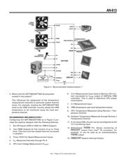
Figure 1. Automatic Fan Control Block Diagram
REV. 0
a
AN-613
APPLICATION NOTE
One Technology Way • P.O. Box 9106 • Norwood, MA 02062-9106 • Tel: 781/329-4700 • Fax: 781/326-8703 • www.analog.com
Programming the Automatic Fan Speed Control Loop
By Mary Burke
AUTOMATIC FAN SPEED CONTROL
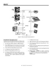
The ADT7460/ADT7463 have a local temperature sensor
and two remote temperature channels that may be con-
nected to an on-chip diode-connected transistor on a
CPU. These three temperature channels may be used as
the basis for automatic fan speed control to drive fans
using pulsewidth modulation (PWM). In general, the
greater the number of fans in a system, the better the
cooling, but this is to the detriment of system acoustics.
Automatic fan speed control reduces acoustic noise
by optimizing fan speed according to measured tem-
perature. Reducing fan speed can also decrease system
current consumption. The automatic fan speed control
mode is very flexible owing to the number of program-
mable parameters, including T
MIN
and T
RANGE
, as
discussed in detail later. The T
MIN
and T
RANGE
values for a
temperature channel and thus for a given fan are critical
since these define the thermal characteristics of the sys-
tem. The thermal validation of the system is one of the
most important steps of the design process, so these
values should be carefully selected.
AIM OF THIS SECTION
The aim of this application note is not only to provide
the system designer with an understanding of the auto-
matic fan control loop, but to also provide step-by-step
guidance as to how to most effectively evaluate and
select the critical system parameters. To optimize the
system characteristics, the designer needs to give some
forethought to how the system will be configured, i.e.,
the number of fans, where they are located, and what
temperatures are being measured in the particular
TACHOMETER 1
MEASUREMENT
RAMP
CONTROL
(ACOUSTIC
ENHANCEMENT
TACHOMETER 2
MEASUREMENT
RAMP
CONTROL
(ACOUSTIC
ENHANCEMENT
TACHOMETER 3
AND 4
MEASUREMENT
PWM
GENERATOR
PWM
CONFIG
PWM
GENERATOR
PWM
CONFIG
RAMP
CONTROL
(ACOUSTIC
ENHANCEMENT
PWM
GENERATOR
PWM
CONFIG
�
PWM
MIN
�
PWM
MIN
�
PWM
MIN
MUX
THERMAL CALIBRATION
100%
0%
T
MIN
T
RANGE
THERMAL CALIBRATION
100%
0%
T
MIN
T
RANGE
THERMAL CALIBRATION
100%
0%
T
MIN
T
RANGE
PWM1
PWM2
PWM3
REMOTE 1
TEMP
LOCAL
TEMP
REMOTE 2
TEMP
Figure 1. Automatic Fan Control Block Diagram
©2008 SCILLC. All rights reserved. Publication Order Number:
April 2008 - Rev. 1 AN613/D