

下载

1 Introduction
2 Overview
3 Required Hardware and Equipment
4 Hardware Setup
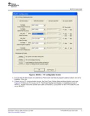
Quick Start Guide
SLEU070A – February 2006 – Revised July 2006
TVP5154EVM Quick Start Guide
The TVP5154EVM refers to both the TVP5154 board and a professional encoder module when they are
connected together. The TVP5154EVM evaluation module is a printed circuit board designed for
evaluation of the TVP5154 quad video decoder and also includes the TMS320DM642 DSP. This quick
start guide outlines the necessary hardware and software setup required to provide full evaluation of the
TVP5154.
The TVP5154EVM allows the user to have up to two composite inputs or one S-video input for each of the
four independent channels. The analog video outputs supported by the EVM include composite, S-video,
and component video (YPbPr). The analog outputs are available simultaneously. The 5-V supply and the
I
2
C signals are shared across a common connector interface along with the necessary data and clocks.
The TVP5154EVM uses the PC parallel port to emulate the I
2
C bus, which provides communication with
the TVP5154 video decoder, DM642 and the video encoder. The WinVCC application software that
communicates with the devices via the I
2
C is provided on the EVM CD-ROM.
The required hardware and equipment necessary to use the TVP5154EVM are:
• TVP5154EVM (provided)
• Universal 5-V power supply (provided)
• Parallel cable (provided)
• Windows-based PC with Win95 or later
• Composite or S-video cables for inputs
• Composite, S-video, or component cable for output
• Video sources (security camera, pattern generator, Quantum generator, DVD player, etc.)
• Display monitor that supports composite, S-video, or component video input
All connectors are labeled according to their function. To prepare the EVM for evaluation, connect the
following:
1. TVP5154 module to encoder module
2. Parallel port cable from TVP5154EVM to the PC
3. Analog video sources to TVP5154EVM inputs
4. Analog video out from TVP5154EVM to monitor
5. 5-V power supply to the dc jack on the TVP5154 board. A green LED on each board should now be lit.
Each input has an anti-alias filter that can be in-circuit or bypassed by jumpers (JP1–JP8). To select the
filter, the shunts need to be positioned to short positions 1-3 and 2-4. To bypass the filter, the shunts need
to be moved to short positions 1-2 and 3-4. The boards are shipped with the filter bypassed.
All trademarks are the property of their respective owners.
SLEU070A – February 2006 – Revised July 2006 TVP5154EVM Quick Start Guide 1
Submit Documentation Feedback