
下载

ADVANCEINFORMATION
Product
Folder
Sample &
Buy
Technical
Documents
Tools &
Software
Support &
Community
TMS320F28377S, TMS320F28376S, TMS320F28375S, TMS320F28374S
SPRS881 –AUGUST 2014
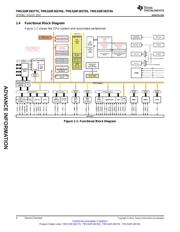
TMS320F2837xS Delfino™ Microcontrollers
1 Device Overview
1.1 Features
1
– Up to Four Serial Communications Interfaces
• TMS320C28x 32-Bit CPU
(SCIs)
– 200 MHz (5-ns Cycle Time)
– Two I
2
C Interfaces
– IEEE 754 Single-Precision Floating-Point Unit
• Analog Subsystem
(FPU)
– Up to Four Dual-Mode Analog-to-Digital
– Trigonometric Math Unit (TMU)
Converters (ADCs)
– Viterbi/Complex Math Unit (VCU-II)
– 16-Bit Mode
– 16 × 16 and 32 × 32 Multiply and Accumulate
• 1.1 MSPS Each (up to 4.4-MSPS System)
(MAC) Operations
• Differential
– 16 × 16 Dual MAC
• External Reference
– Three 32-Bit CPU Timers
• Up to 12 External Channels
– Harvard Bus Architecture
– 12-Bit Mode
– Fast Interrupt Response and Processing
• 3.5 MSPS Each (up to 14-MSPS System)
– Unified Memory Programming Model
• Single-Ended or Differential
• Programmable Control Law Accelerator (CLA)
• External Reference
– 200 MHz (5-ns Cycle Time)
• Up to 24 External Channels
– 32-Bit Floating-Point Math Accelerator
(IEEE 754 Single Precision)
– Single Sample-and-Hold (S/H) on Each ADC
– Executes Code Independently of Main CPU
– Integrated Post-Processing of ADC Conversions
• On-Chip Memory
• Saturating Offset Calibration
– Up to 1MB of Flash, Up to 164KB of RAM
• Error From Setpoint Calculation
– Boot ROM (64KB)
• High, Low, and Zero-Crossing Compare,
With Interrupt Capability
• Serial Peripheral Interface (SPI), Inter-
Integrated Circuit (I
2
C), Controller Area
• Trigger-to-Sample Delay Capture
Network (CAN), and Parallel I/O Software
– Analog Comparator/Digital-to-Analog Converter
Boot Modes
(DAC) Subsystem With Glitch Filter, for
• Standard Math Tables
Windowed Trip Monitor and Peak Current Mode
Control (PCMC) Interfaces
• System Peripherals
• Eight Windowed Comparators With 12-Bit
– Two External Memory Interfaces (EMIFs) With
DAC References
ASRAM and SDRAM Support
– Three 12-Bit Buffered DAC Outputs
– 6-Channel Direct Memory Access (DMA)
Controller
• Enhanced Control Peripherals
– Up to 169 Individually Programmable,
– Up to 24 PWM Channels With Enhanced
Multiplexed General-Purpose Input/Output
Features
(GPIO) Pins With Input Filtering
– Up to 16 High-Resolution Pulse Width
• Communications Peripherals
Modulator (HRPWM) Channels
– USB 2.0 + PHY Port
• High Resolution on Both A and B Channels
of 8 PWM Modules
– Support for 12-Pin 3.3 V-Compatible Universal
Parallel Port (uPP) Interface
• Dead-Band Support (on Both Standard and
High Resolution)
– Two CAN-Bus Ports (32 Mailboxes Each)
– Six Enhanced Capture (eCAP) Modules
– Three High-Speed (40-MHz) SPI Ports With
16-Level FIFO, DMA Support, and
– Up to Three Enhanced Quadrature Encoder
CLA-Accessible
Pulse (eQEP) Modules
– Two Multichannel Buffered Serial Ports
– Two Sigma-Delta Filter Module (SDFMs) With
(McBSPs)
up to 8 Input Channels, and Pulse Width
Modulator (PWM) Synchronization
1
An IMPORTANT NOTICE at the end of this data sheet addresses availability, warranty, changes, use in safety-critical applications,
intellectual property matters and other important disclaimers. ADVANCE INFORMATION for pre-production products; subject to
change without notice.