
下载

Maxim > Design Support > Technical Documents > Tutorials > Interface Circuits > APP 763
Keywords: RS-485, rs485, EIA/TIA-485, differential data, network wiring, balanced line, common-mode
rejection, CMR noise cancellation, EMI, twisted pair, unit load, termination resistor
TUTORIAL 763
Guidelines for Proper Wiring of an RS-485
(TIA/EIA-485-A) Network
Nov 19, 2001
Abstract: The proper method of wiring an RS-485 network is described, with recommendations for
twisted-pair cabling and correctly locating termination resistors. Received waveforms are shown for
examples of proper and improper cable termination. Configurations are shown for a simple, single-
transmitter/multiple receiver network through multiple transceiver to multibranched circuits.
This application note provides basic guidelines for wiring an RS-485 network. The RS-485 specification
(officially called TIA/EIA-485-A) does not specifically explain out how an RS-485 network should be
wired. The specification does, nonetheless, give some guidelines. These guidelines and sound
engineering practices are the basis of this note. The suggestions here, however, are by no means
inclusive of all the different ways that a network can be designed.
RS-485 transmits digital information between multiple locations. Data rates can be up to, and sometimes
greater than, 10Mbps. RS-485 is designed to transmit this information over significant lengths, and 1000
meters are well within its capability. The distance and the data rate with which RS-485 can be
successfully used depend a great deal on the wiring of the system.
Wire
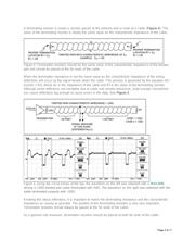
RS-485 is designed to be a balanced system. Simply put, this means there are two wires, other than
ground, that are used to transmit the signal.
Figure 1. A balanced system uses two wires, other than ground, to transmit data.
Page 1 of 11