
下载

User's Guide
SNOA485A–March 2007–Revised May 2013
AN-1602 LMH7322 Dual Comparator Evaluation Board
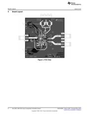
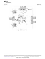
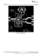
1 General Description
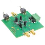
This board is designed to demonstrate the LMH7322 dual comparator with RSPECL outputs. It will
facilitate the evaluation of the LMH7322 in most of the possible configurations. There is one part
containing two comparators mounted onto this board. The intention of this board is to demonstrate the
conversion of an analog signal to a digital presentation at LVDS levels and to translate this LVDS signal to
RSECL levels. The LATCH function can be evaluated using the two switches mounted on the edge of the
board. Two test points located between the comparators allows checking the LVDS levels while the output
signals are fed to two SMA connectors that feed the signals on a 50 Ω basis to any scope or analyzer. To
demonstrate the hysteresis functionality both hysteresis resistors are mounted on header pins, which
makes them changeable in a convenient manner. Only two supply voltages are needed to make this setup
work. The positive supply is +2.5 V and the negative supply is −5.2 V.
2 Basic Operation
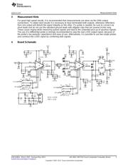
The complete schematic consists of two comparators that show the conversion of analog to LVDS and
LVDS to RSECL levels.
2.1 Input Conditions
The input signal is connected to an SMA connector and feed to the non-inverting input of the first
comparator. This is a DC path and referenced to ground by a 50 Ω (R3) resistor. The inverting input is
also referenced to ground via a 50 Ω (R4) resistor. If no signal is present and both inputs are referenced
to the same voltage, the comparator may oscillate if no precautions are taken. Adding a hysteresis resistor
introduces a small voltage around the trip point, which prevents the input stage from continuously
switching due to noise or other uncontrolled events. The hysteresis voltage can be varied by changing the
resistor value connected to J3 (input stage) or J4 (output stage). The resistor can be varied between its
extremes of being shorted or being open. Both situations are allowed. The short means that the highest
hysteresis voltage is set and an open connection means that there is no hysteresis voltage set. This last
situation means that there is the highest risk for oscillations if no signal or a very small signal is applied. It
is desirable to use some hysteresis while working with very small and/ or low frequency signals.
2.2 The Latch Function
Both comparators of the LMH7322 have a separate LATCH function, which means that every comparator
can be activated or deactivated by a separate LATCH signal. Both latch functions use complementary
signals and are connected to the two mini-switches (S1 and S2) situated on the border of the printed
circuit board (PCB). If these switches are placed in the ‘ON’ state, the latch function is active and the
outputs are frozen.
All trademarks are the property of their respective owners.
1
SNOA485A–March 2007–Revised May 2013 AN-1602 LMH7322 Dual Comparator Evaluation Board
Submit Documentation Feedback
Copyright © 2007–2013, Texas Instruments Incorporated