
下载

1 Introduction
1.1 Overview
User's Guide
SLLU091 – January 2006
ISO721EVM
Contents
1 Introduction ................................................................................................................... 1
2 EVM Setup and Operation .................................................................................................. 3
List of Figures
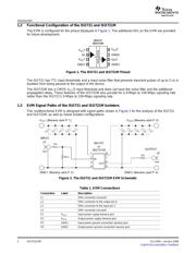
1 The ISO721 and ISO721M Pinout ......................................................................................... 2
2 The ISO721 and ISO721M EVM Schematic ............................................................................. 2
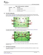
3 ISO721 and ISO721M EVM, Top ......................................................................................... 3
4 ISO721 and ISO721M EVM, Bottom ..................................................................................... 3
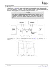
5 Basic EVM Operation ....................................................................................................... 4
6 Typical Input and Output Waveforms ..................................................................................... 4
List of Tables
1 EVM Connections ............................................................................................................ 2
This user's guide details the evaluation module (EVM) operation of the ISO721 and ISO721M digital
isolators. The same EVM board is used for each device. Configuration requirements are presented as well
as user optional I/O loads. This document is intended to aid designers with isolator parameter
performance evaluation within a particular system.
The ISO721 and ISO721M digital isolators have a logic input and output buffer separated by a silicon
oxide (SiO
2
) insulation barrier. Used with isolated power supplies, these devices prevent noise currents on
a data bus or other circuits from entering the local ground and interfering with or damaging sensitive
circuitry.
A binary input signal is conditioned, translated to a balanced signal, and then differentiated by the
capacitive isolation barrier. Across the isolation barrier, a differential comparator receives the logic
transition information, then sets or resets a flip-flop and the output circuit accordingly. A periodic update
pulse is sent across the barrier to ensure the proper dc level of the output. If this dc-refresh pulse is not
received for more than 4 μ s, the input is assumed to be unpowered or not functional, and the fail-safe
circuit drives the output to a logic-high state.
CAUTION
Note that although these devices provide galvanic isolation of up to 4000 V, this
EVM cannot be used for isolation voltage testing. It is designed for the
examination of device operating parameters only and will be damaged if high
voltage (> 5.5 V) is applied anywhere in the circuit.
SLLU091 – January 2006 ISO721EVM 1
Submit Documentation Feedback