

下载

Maxim > Design Support > Technical Documents > Reference Schematics > 1-Wire
®
Devices > APP 244
Maxim > Design Support > Technical Documents > Reference Schematics > iButton
®
> APP 244
Maxim > Design Support > Technical Documents > Reference Schematics > Microcontrollers > APP 244
Keywords: 1-Wire master, microcontroller, network driver
REFERENCE SCHEMATIC 244
Advanced 1-Wire Network Driver
By: Bernhard Linke, Principal Member Technical Staff
May 30, 2003
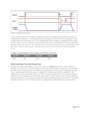
Abstract: This document describes a microcontroller-based 1-Wire
®
master interface for reliable
operation of small, medium, and large 1-Wire networks. This is accomplished using careful impedance
matching, intelligent (software-controlled) active pullup, and slew-rate control. Software flow charts are
included to assist the user in generating the correct 1-Wire timing for reset pulse, presence detect, write
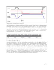
one, write zero, and read time slots using any suitable microcontroller. Scope traces illustrate the timing
performance of the driver as well as transmission line effects as they appear with long cables.
Introduction
To a large degree, the reliability of a 1-Wire network depends on the characteristics of the driver circuit
that the host computer uses to communicate with 1-Wire slave devices. This document describes a 1-
Wire master interface that uses careful impedance matching and an "intelligent" (software-controlled)
strong pullup to accomplish reliable operation in networks from very lightweight to very heavy, up to
500m equivalent size. For guidelines on how to create reliable 1-Wire networks see tutorial 148,
"Guidelines for Reliable Long Line 1-Wire Networks".
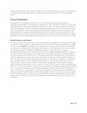
Circuit Description
The network driver (Figure 1) consists of a pulldown section (Q1, R1, C1, R5) and a pullup section (Q2,
R2, C2, R6). A third transistor and surrounding components (Q3, C4, R7) form a strong pullup section to
supply extra power for devices such as EEPROMs, or temperature sensors. This "strong-pullup" function
is not discussed in this document. Of the three transistors, a maximum of one is conducting at any time.
When there is no 1-Wire communication ("idle" state), all three transistors are nonconducting.
Page 1 of 15