


下载

Application Note Please read the Important Notice and Warnings at the end of this document Revision 1.0
www.infineon.com 2016-11-14
AN_REF_201610_PL21_002
45 W 20 V adapter reference board
with ICE2QS03G, IPA60R650CE, BAS21-03W and 2N7002
About this document
Scope and purpose
This document is an engineering report that describes a 45 W 20 V adapter reference design board using a
quasi-resonant PWM IC ICE2QS03G (DSO-8) with a CoolMOS™ IPA60R650CE (TO220FP). The reference adapter
board is designed to fit a very small form factor while having high efficiency, low standby power and various
modes of protection for a highly reliable system. The board passes EMI (both conducted and radiated), ESD
immunity and surge immunity tests and can be used for production by customers after final verification with
minor changes.
Intended audience
This document is intended for power supply designers, application engineers, students, etc., who wish to
design a high efficiency, high reliability and very small form factor 45 W 20 V AC-DC adapter in a short period of
time, using Infineon's CoolMOS™ CE series and quasi-resonant PWM IC ICE2QS03G.
Table of contents
About this document .............................................................................................................................................1
Table of contents...................................................................................................................................................1
1 Abstract..............................................................................................................................................3
2 Reference board.................................................................................................................................4
3 Specification of reference board........................................................................................................5
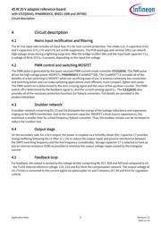
4 Circuit description..............................................................................................................................6
4.1 Mains input rectification and filtering ....................................................................................................6
4.2 PWM control and switching MOSFET......................................................................................................6
4.3 Snubber network.....................................................................................................................................6
4.4 Output stage............................................................................................................................................6
4.5 Feedback loop .........................................................................................................................................6
5 Circuit operation ................................................................................................................................7
5.1 Startup operation....................................................................................................................................7
5.2 Normal mode operation .........................................................................................................................7
5.3 Primary side peak current control..........................................................................................................7
5.4 Digital frequency reduction ....................................................................................................................7
5.5 Burst mode operation.............................................................................................................................7
6 Protection features ............................................................................................................................9
6.1 V
CC
over voltage and under voltage protection......................................................................................9
6.2 Over load/open loop protection.............................................................................................................9
6.3 Auto restart for over temperature protection........................................................................................9
6.4 Adjustable output overvoltage protection.............................................................................................9
6.5 Short winding protection........................................................................................................................9
6.6 Foldback point protection ......................................................................................................................9
6.7 Line under voltage protection (brownout) by external circuit..............................................................9
7 Circuit diagram ................................................................................................................................11
8 PCB layout........................................................................................................................................12