

下载

1 Introduction
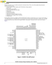
This application note describes external hardware required by
different modules of S12ZVH family of MCUs. The S12ZVH
family was designed to be used in basic/low automotive
instrumentation clusters that include analog stepper motors, an
LCD, and/or CAN communications. This application note will
cover details on the following modules and pins: the Voltage
Regulator, Reset Circuitry, ADC module, Battery Sensing
module, high current pins, interrupt pins, unused pins, and the
CANPHY module, including its dedicated voltage regulator.
This note also covers general PCB layout recommendations
that help reduce electromagnetic emissions and improve
electromagnetic immunity.
As the S12ZVH family is aimed at automotive instrumentation
clusters, we will analyze the different requirements for this
application in terms of external hardware required for its
operation, and the advantages this family offers over typical
solutions. For more specific information about this family of
MCUs and their features, refer to http://www.freescale.com/
S12ZVH.
Some external hardware like capacitors and resistors are
needed to ensure proper operation of the different modules in
the MCU. The most common configurations include current
limiter circuits, debounce capacitors, pull resistors, filter and
bulk capacitors, and inductors, among others. These electronic
configurations are needed depending on the application to be
Freescale Semiconductor
Document Number:AN4721
Application Note
Rev 0, 08/2013
S12ZVH: Hardware Design
Guidelines
by:
Arturo Inzunza
© 2013 Freescale Semiconductor, Inc.
Contents
1 Introduction............................................................1
2 Voltage regulators...................................................3
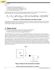
3 Reset circuit............................................................6
4 Programming circuit...............................................7
5 Clock circuit............................................................7
6 Interrupt pins...........................................................9
7 LCD pins and contrast.............................................9
8 Special and unused pins..........................................9
9 High-Current pins.................................................10
10 Analog pins and battery sensing............................10
11 CANPHY...............................................................10
12 Printed circuit board design
recommendations...................................................11
13 Conclusion.............................................................12
14 References.............................................................12