
下载
AN-1177
APPLICATION NOTE
One Technology Way • P. O. Box 9106 • Norwood, MA 02062-9106, U.S.A. • Tel: 781.329.4700 • Fax: 781.461.3113 • www.analog.com
LVDS and M-LVDS Circuit Implementation Guide
by Dr. Conal Watterson
Rev. 0 | Page 1 of 12
INTRODUCTION
Low voltage differential signaling (LVDS) is a standard for
communicating at high speed in point-to-point applications.
Multipoint LVDS (M-LVDS) is a similar standard for multi-
point applications. Both LVDS and M-LVDS use differential
signaling, a two-wire communication method where receivers
detect data based on the voltage difference between two
complementary electrical signals. This greatly improves noise
immunity and minimizes emissions.
LVDS
LVDS is a lower power alternative to emitter-coupled logic
(ECL) or positive emitter-coupled logic (PECL).The primary
standard for LVDS is TIA/EIA-644. An alternative standard
sometimes used for LVDS is IEEE 1596.3—SCI, scalable
coherent interface. LVDS has been widely adopted for high-
speed backplane, cabled, and board-to-board data transmission
and clock distribution, as well as communication links within a
single PCB.
Advantages of LVDS include
• Communication at speeds of up to 1 Gbps or more
• Reduced electromagnetic emissions
• Increased immunity to noise
• Low power operation
• Common-mode range allowing differences of up to ±1 V
in ground offset
M-LVDS
The standard TIA/EIA-899 for multipoint low voltage differ-
ential signaling (M-LVDS) extends LVDS to address multipoint
applications. M-LVDS allows higher speed communication
links than TIA/EIA-485 (RS-485) or controller area network
(CAN) with lower power. See the References section for a list of
the standards referred to in this application note.
Additional features of M-LVDS over LVDS include
• Increased driver output strength
• Controlled transition times
• Extended common-mode range
• Option of failsafe receivers for bus idle condition
LVDS/M-LVDS APPLICATION CONSIDERATIONS
This application note considers the following aspects
concerning LVDS/M-LVDS circuit implementation:
• Bus types and topologies
• Clock distribution applications
• Characteristics of LVDS/M-LVDS signaling
• Terminati on and PCB layout
• Jitter and skew
• Data encoding and synchronization
• Isolation
WHY USE LVDS OR M-LVDS?
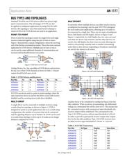
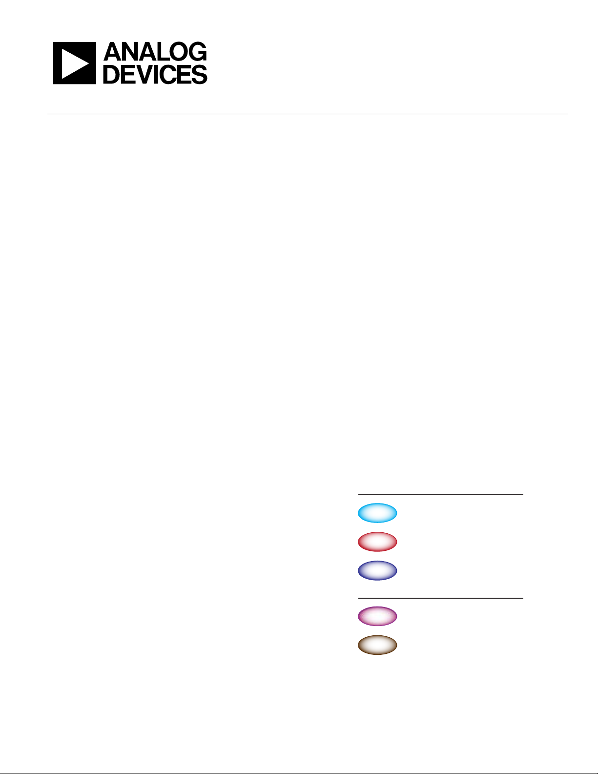
LVDS and M-LVDS are compared to other multipoint and point-
to-point protocols in Figure 1. Both standards have low power
requirements. LVDS and M-LVDS are characterized by differential
signaling with a low differential voltage swing. M-LVDS specifies
an increased differential output voltage compared to LVDS in order
to allow for the increased load from a multipoint bus.
Both protocols are designed for high-speed communication.
Typical applications utilize PCB traces or short wired/backplane
links. The common mode range of LVDS is designed for these
applications. M-LVDS has an extended common mode range
compared to LVDS to allow for the additional noise in a multipoint
topology.
LONG DISTANCES (>1km)
TYP. MAX. DATA RATE: 16Mbps
RS-485
MEDIUM DISTANCES (MAX. 40m)
ROBUST PROTOCOL
MAX. DATA RATE: 1Mbps
CAN
MULTIPOINT
MEDIUM DISTANCES (MAX. 20m TO 40m)
LOW POWER, HIGH SPEED
TYP. DATA RATE: 100Mbps, 200Mbps
M-LVDS
SHORT DISTANCES (MAX. 5m TO 10m)
LOW POWER, HIGH SPEED
MAX. DATA RATE: >1Gbps
LVDS
SHORT DISTANCES
HIGH SPEED
MAX. DATA RATE: ~3Gbps
PECL
POINT-TO-POINT
11236-001
Figure 1. Comparison of Communication Standards