
下载
8-/10-Lead PulSAR User Guide
UG-340
One Technology Way • P. O. Box 9106 • Norwood, MA 02062-9106, U.S.A. • Te l: 781.329.4700 • Fax: 781.461.3113 • www.analog.com
Evaluation Board for the 8-/10-Lead Family of 14-/16-/18-Bit PulSAR ADCs
PLEASE SEE THE LAST PAGE FOR AN IMPORTANT
WARNING AND LEGAL TERMS AND CONDITIONS.
Rev. C | Page 1 of 31
FEATURES
Full featured evaluation board for 8-/10-lead PulSAR ADCs
Versatile analog signal conditioning circuitry
On-board reference, reference buffers, and ADC drivers
PC software for control and data analysis of time and
frequency domain
System demonstration platform compatible (EVAL-SDP-CB1Z)
EQUIPMENT NEEDED
Evaluation board (see Table 5)
Wall adapter power supply
Additional equipment needed
SDP board (EVAL-SDP-CB1Z) (optional)
Precision source
Cable (SMA input to evaluation board)
GENERAL DESCRIPTION
The 10-lead PulSAR® evaluation board covers the following
10-lead PulSAR analog-to-digital converters (ADCs): AD7685
(16-bit), AD7686 (16-bit), AD7687 (16-bit), AD7688 (16-bit),
AD7690 (18-bit), AD7691 (18-bit), AD7693 (16-bit), AD7942
(14-bit), AD7946 (14-bit), AD7980 (16-bit), AD7982 (18-bit),
AD7983 (16-bit), AD7984 (18-bit), AD7988-5 (16-bit), AD7989-5
(18-bit), AD7915 (16-bit) and AD7916 (16-bit).
The 8-lead PulSAR evaluation board covers the following 8-lead
PulSAR ADCs: AD7683 (16-bit), AD7684 (16-bit), and AD7694
(16-bit).
These low power ADCs offer very high performance of up to
18 bits with throughputs ranging from 100 kSPS to 1.33 MSPS.
The evaluation board is designed to demonstrate the performance
of the ADCs and to provide an easy to understand interface
for a variety of system applications. A full description of these
products is available in their respective data sheets, which
should be consulted when using this evaluation board.
The evaluation board is ideal for use with Analog Devices, Inc.,
system demonstration platform (SDP). This evaluation board
interfaces to the SDP board via a 120-pin connector. SMA
connectors, J6 and J10, are provided for the low noise analog
signal source.
On-board components include a high precision buffered band gap
5.0 V reference (ADR435), a signal conditioning circuit with two
op amps (ADA4841-1), and a power supply to derive the necessary
voltage levels to supply all voltage needs. The 8-lead board also
includes a level shifter (ADG3304) to interface the ADC with
the EVAL-SDP-CB1Z.
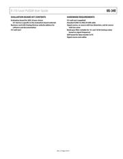
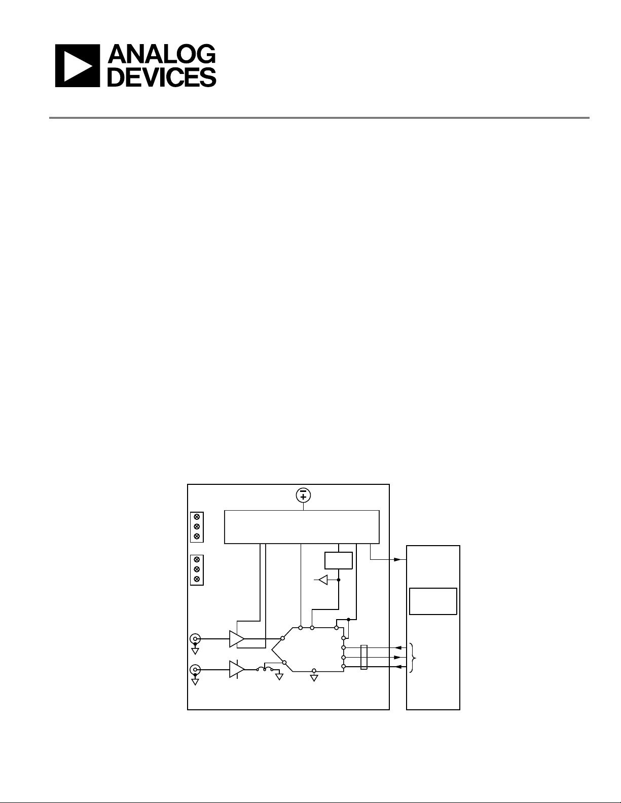
SIMPLIFIED EVALUATION BOARD BLOCK DIAGRAM
SDP BOARD10-LEAD PulSAR EVALUATION BOARD
VIN+
VIN–
IN+
IN–
ADC
+V
S
–V
S
GND
5V
ADSP-BF527
DSP
SPORT
SCK
SDO
CNV
OVDD
SDI
REF
+7.5V
VDD
ADA4841-1
ADA4841-1
AB
–2.5V
–2.5V
+7.5V
GND
VCM
AD8031
POWER SUPPLY CIRCUITRY
ADP7102, ADP7104, ADP2301
VIN = 9V
WALL ADAPTER
VDD
VSDP
GND
(OPTIONAL)
(OPTIONAL)
+7.5V/-2.5V 2.5V/5V +7.5V 3.3V +5V
ADR435
5V
GLUE
LOGIC
10322-001
Figure 1.