
下载
DN-33
Design Note
OPTOCOUPLER FEEDBACK DRIVE TECHNIQUES
USING THE UC 3901 AND UC3903
Numerous techniques and devices are available to
the designers of optocoupler feedback circuits. The
more traditional approaches utilize either an
adjustable shunt regulator like the TL431 device or
an op-amp and voltage reference as the optocoupler
driver. While these approaches do satisfy the basic
requirements in many applications, quite often they
lack the performance that is achievable from a more
sophisticated circuit. Too often, these low cost
solutions necessitate additional protection circuitry
elsewhere in the control circuit to overcome the
deficiencies in the feedback path.
A variety of low cost supervisory ICs contain the
required building blocks for the more demanding
optocoupler feedback drive applications. Initially
developed to address other specific power supply
tasks, several control ICs excel in the role as
precision optocoupler control and drivers.
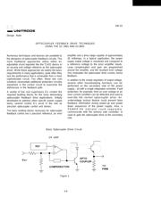
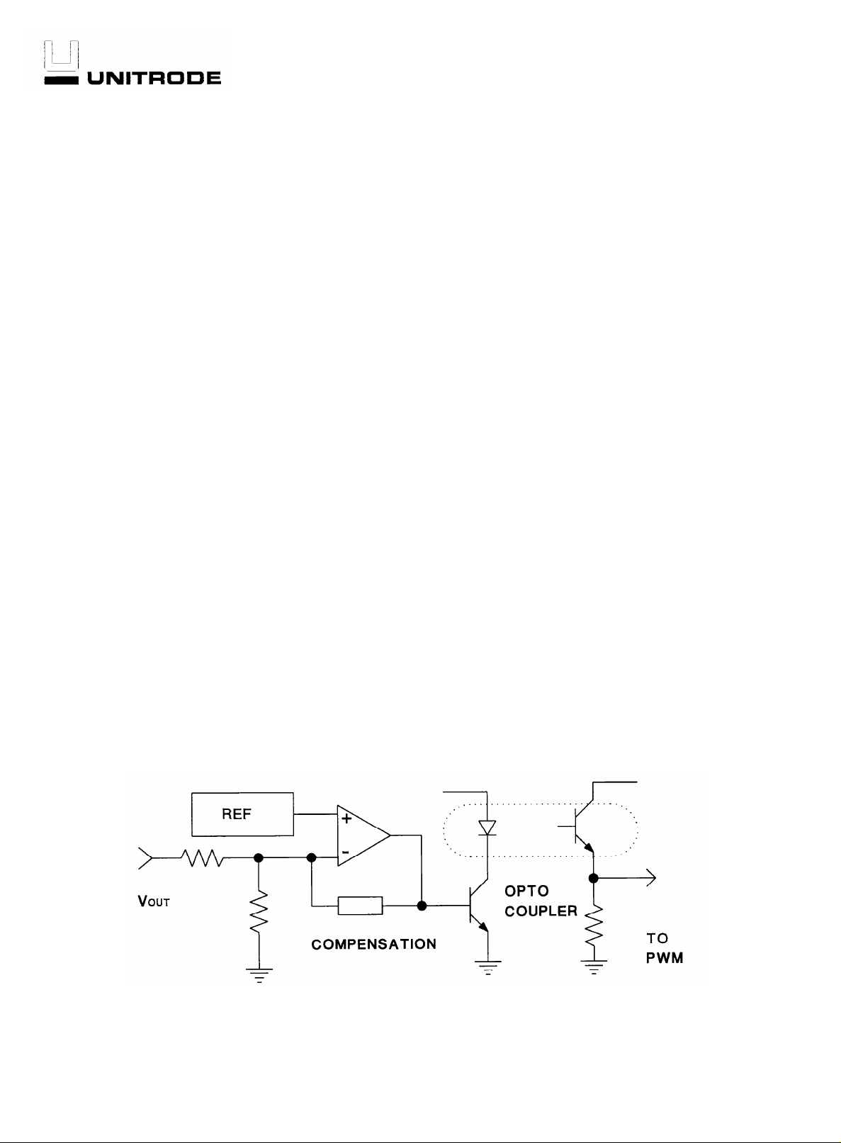
The basic building blocks necessary for optocoupler
feedback control are a precision reference, an error
amplifier and a drive stage capable of approximately
20 milliamps. In a typical application, the power
supply output voltage is monitored and compared to
a reference voltage to the error amplifier inputs.
Loop compensation and gain are programmed
around the amplifier, and the resultant error voltage
(Ve) modulates the optocoupler drive current, hence
feedback.
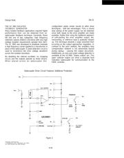
In addition to the simple regulation of output voltage,
several other housekeeping functions can be
performed on the secondary side of the power
supply - all with a single integrated controller. Fault
protection, for example, from an over voltage or an
over current condition can be detected and used to
override the normal optocoupler drive. An
undervoltage lockout feature could prevent false
feedback information during power-up and power
down sequences of the power supply. Also, a
POWER-OK indicator could separately
communicate with the primary side controller, or
used to gate the optocoupler drive at the secondary
side.
Basic Optocoupler Driver Circuit
OP AMP
Figure 1.
4-9