
下载
REV. 0
a
AN-581
APPLICATION NOTE
One Technology Way • P.O. Box 9106 • Norwood, MA 02062-9106 • Tel: 781/329-4700 • Fax: 781/326-8703 • www.analog.com
Biasing and Decoupling Op Amps
in Single Supply Applications
by Charles Kitchin
© Analog Devices, Inc., 2002
SINGLE OR DUAL SUPPLY?
Battery-powered op amp applications such as those
found in automotive and marine equipment have only a
single available power source. Other applications, such
as computers, may operate from the ac power lines but
still have only a single polarity power source, such as
5 V or 12 V dc. Therefore, it is often a practical necessity
to power op amp circuits from a single polarity supply.
But single supply operation does have its drawbacks: it
requires additional passive components in each stage
and, if not properly executed, can lead to serious insta-
bility problems.
COMMON PROBLEMS WITH RESISTOR BIASING
Single supply applications have inherent problems that
are not usually found in dual supply op amp circuits. The
fundamental problem is that an op amp is a dual supply
device and so some type of biasing, using external com-
ponents, must be used to center the op amp’s output
voltage at midsupply. This allows the maximum input
and output voltage swing for a given supply voltage.
In some low gain applications, where input signals are
very small, the op amp’s output can be lifted above
ground by only 2 V or 3 V. But in most cases, all clipping
needs to be avoided and so the output needs to be cen-
tered around midsupply.
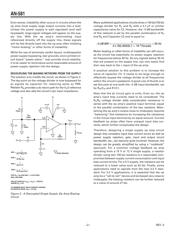
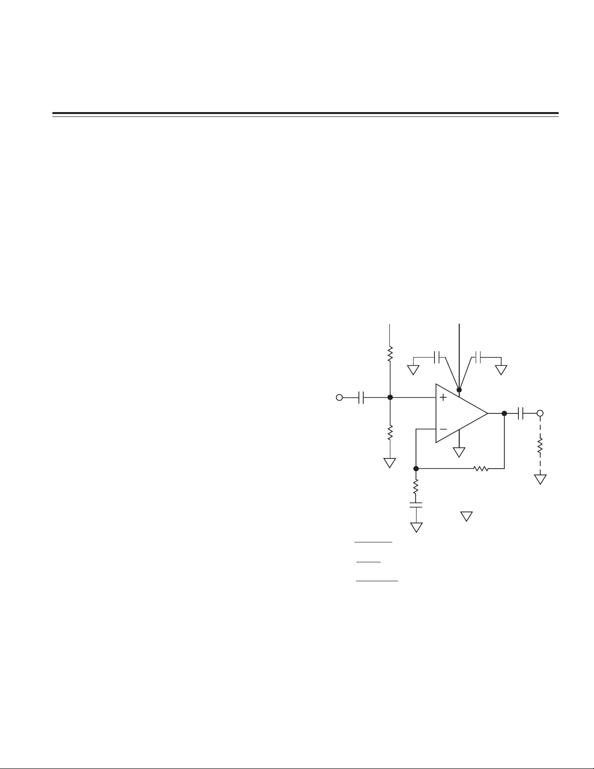
The circuit of Figure 1 shows a simple single supply
biasing method. This noninverting, ac-coupled, ampli-
fier circuit uses a resistor divider with two biasing
resistors, R
A
and R
B
, to set the voltage on the noninvert-
ing equal to V
S
/2. As shown, the input signal, V
IN
, is
capacitively coupled to the noninverting input terminal.
This simple circuit has some serious limitations. One is
that the op amp’s power supply rejection is almost entirely
gone, as any change in supply voltage will directly
change the V
S
/2 biasing voltage set by the resistor divider.
Power Supply Rejection (PSR) is a very important (and
frequently overlooked) op amp characteristic.
Since a one volt change on the supply line causes a
one-half volt change at the output of the divider, the
circuit’s PSR is only 6 dB. So, the normally high power
supply rejection provided by any modern op amp,
which greatly reduces any ac signals (and power sup-
ply hum) from feeding into the op amp via its supply
line, is now gone.
0.1F
1F
V
S
R2
R1
C1
*STAR GROUND
C
OUT
V
OUT
R
LOAD
V
S
/2
V
S
/2
R
A
100k
R
B
100k
*
*
V
S
C
IN
V
IN
π ( )
BW1
=
1
2
π 1/2R
A
C
IN
BW2 =
1
2
π R1 C1
BW3 =
1
2
π R
LOAD
C
OUT
FOR R
A
= R
B
FOR AC SIGNALS, V
OUT
= V
IN
(1 + (R2/R1))
WHERE X
C1
<<
R1
*
*
Figure 1. A Potentially Unstable Single Supply Op
Amp Circuit