
下载

Maxim > Design Support > Technical Documents > Application Notes > Communications Circuits > APP 1752
Keywords: HSTL, PECL, high speed, interface standards, differential HSTL, high speed transceiver logic,
Jedec standard, Jedec std, differential
APPLICATION NOTE 1752
Applying HSTL Signals to PECL Input Devices
Feb 18, 2003
Abstract: This application note discusses the conditions for interfacing differential HSTL (High-Speed
Transceiver Logic) outputs to PECL (Positive Emitter Coupled Logic) inputs.
PECL and HSTL are two of the high-speed interface standards in common use. PECL (positive supply
referred ECL) is an older standard than HSTL and was developed as a higher speed alternative to the
TTL logic standards. HSTL was defined as an interface standard for digital integrated circuits. The two
standards are not directly compatible. Some PECL devices can receive differential HSTL signals but
careful examination of the HSTL output specifications and PECL input specifications is needed in order
to guarantee operation. Typically, such PECL devices can only receive HSTL signals that have been
transmitted over a short distance. This application note describes the specification criteria required for
direct connection of ICs with HSTL compliant outputs to devices with PECL inputs.
What is HSTL?
High-Speed Transceiver Logic (HSTL) is a 1.5V output buffer supply referenced interface standard for
digital integrated circuits. HSTL can be implemented in both single ended and differential forms and is
intended to be a technology independent standard, suitable for use with CMOS and Bipolar ICs. Jedec
Standard EIA/JESD8-6 describes the functional and parametric constraints required for HSTL
compliance.
EIA/JESD8-6 describes a nominal 1.5V output buffer supply voltage (Vddq) based interface in which
Vddq is independent of the main IC supply voltage. The HSTL input reference voltage (Vref) is nominally
half of Vddq. Single-ended HSTL input and output levels are then defined in relation to Vref and Vddq.
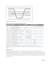
Further, EIA/JESD8-6 defines both DC and AC input and output levels as a means of guaranteeing
performance under AC conditions. Figure 1 shows the HSTL I/O levels in diagramatic form. Table 1
tabulates some key HSTL input and output specifications.
Page 1 of 7