
下载

Maxim > Design Support > Technical Documents > Application Notes > Battery Management > APP 968
Keywords: voltage monitor, voltage detector, voltage converter, charge-pump inverter, voltage tripler
APPLICATION NOTE 968
Load-Disconnect Switch Halts Battery Discharge to
Protect Rechargeable Batteries
Jul 09, 1998
Abstract: This design idea shows a voltage detector, the MAX8211, and charge pump inverter, the
MAX680, that form a load-disconnect switch. This load-detect switch uses only 8µA and halts battery
discharge to protect rechargeable batteries from deep discharge.
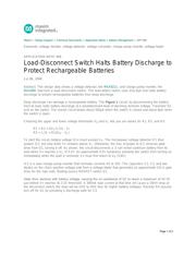
Deep discharge can damage a rechargeable battery. The Figure 1 circuit, by disconnecting the battery
from its load, halts battery discharge at a predetermined level of declining terminal voltage. Transistor Q1
acts as the switch. The overall circuit draws about 500µA when the switch is closed and about 8µA when
the switch is open.
Choosing the upper and lower voltage thresholds V
U
and V
L
lets you set values for R1, R2, and R3:
R1 = R2 × [(V
L
/1.15) - 1]
R3 = 1.15 × R1/(V
U
- V
L
)
To start the circuit, battery voltage (V+) must exceed V
U
. The micropower voltage detector IC1 then
powers IC2, but only while V+ remains above V
L
. Otherwise, the loss of power to IC2 removes gate
drive from Q1, turning it off. As shown, the circuit disconnects a 3-cell nickel-cadmium battery from its
load when V+ reaches a V
L
of 3.1V. An approximate 0.5V hysteresis prevents the switch from turning on
immediately when the load is removed; V+ must first return to V
U
(3.6V).
IC2 is a dual charge-pump inverter that normally converts 5V to 10V. The capacitors C2, C3, and two
diodes on the chip's positive-voltage side form a voltage tripler that generates an approximate 2(V+) gate
drive for the high-side, floating-source MOSFET switch Q1.
Gate drive declines with battery voltage, causing the on-resistance of Q1 to reach a maximum of ≈0.1Ω
just before V+ reaches its 3.1V threshold. A 300mA load current at that time will cause a 30mV drop at
the disconnect switch; the drop will be 2mV to 3mV less for higher battery voltages. Resistor R4 assures
turn-off for Q1 by providing a discharge path for C3.
Page 1 of 2