
下载
Maxim > Design Support > Technical Documents > Application Notes > Power-Supply Circuits > APP 1170
Keywords: boost converters, boost controllers, step-up, step up, pulse frequency modulation, PFM, DC-
DC, dc dc, controllers, current mode
APPLICATION NOTE 1170
Circuit Connection Adds Current-Mode Operation
to PFM Boost Converters
Sep 10, 2002
Abstract: Maxim's PFM boost controllers offer high efficiency and low quiescent current; however, by
externally adding a current mode signal into the feedback, the stability and output ripple are improved.
This circuit connection requires no additional ICs or components versus the standard connection.
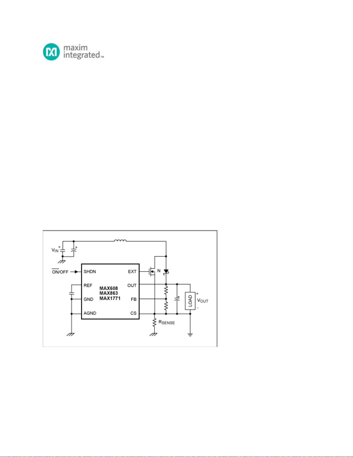
A control scheme used in certain boost-controller ICs from Maxim (current-limited pulse-frequency
modulation, or PFM), achieves high efficiency over a wide range of output current by combining the low
quiescent current of PFM with the load-driving capability of pulse-width modulation (PWM). To provide
current-mode control as well, simply connect the load, output filter capacitor, and lower feedback resistor
to the current-sense pin (CS) instead of ground (Figure 1).
Figure 1. This circuit adds current-mode operation to Maxim's current-limited PFM boost controllers
without increasing the quiescent current.
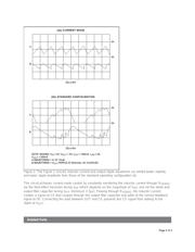
When operating with medium to heavy loads, the Figure 1 circuit exhibits lower output ripple and a more
stable inductor current (Figure 2a) than do the standard application circuits represented by typical
waveforms in Figure 2b. The improvements gained by these connections have no effect on the
quiescent current and require no additional circuitry, but they do require separate input and output
grounds as shown, connected only by R
SENSE
.
Page 1 of 3