
下载
Maxim > Design Support > Technical Documents > Application Notes > A/D and D/A Conversion/Sampling Circuits > APP 1085
Maxim > Design Support > Technical Documents > Application Notes > Amplifier and Comparator Circuits > APP 1085
Maxim > Design Support > Technical Documents > Application Notes > Analog Switches and Multiplexers > APP 1085
Keywords: 4-20mA, 0-20mA, current loop, current loop transmission, DAC, V/I, V to I, converter, digital to
analog converter
APPLICATION NOTE 1085
Selectable-Range Current Loop
May 31, 2002
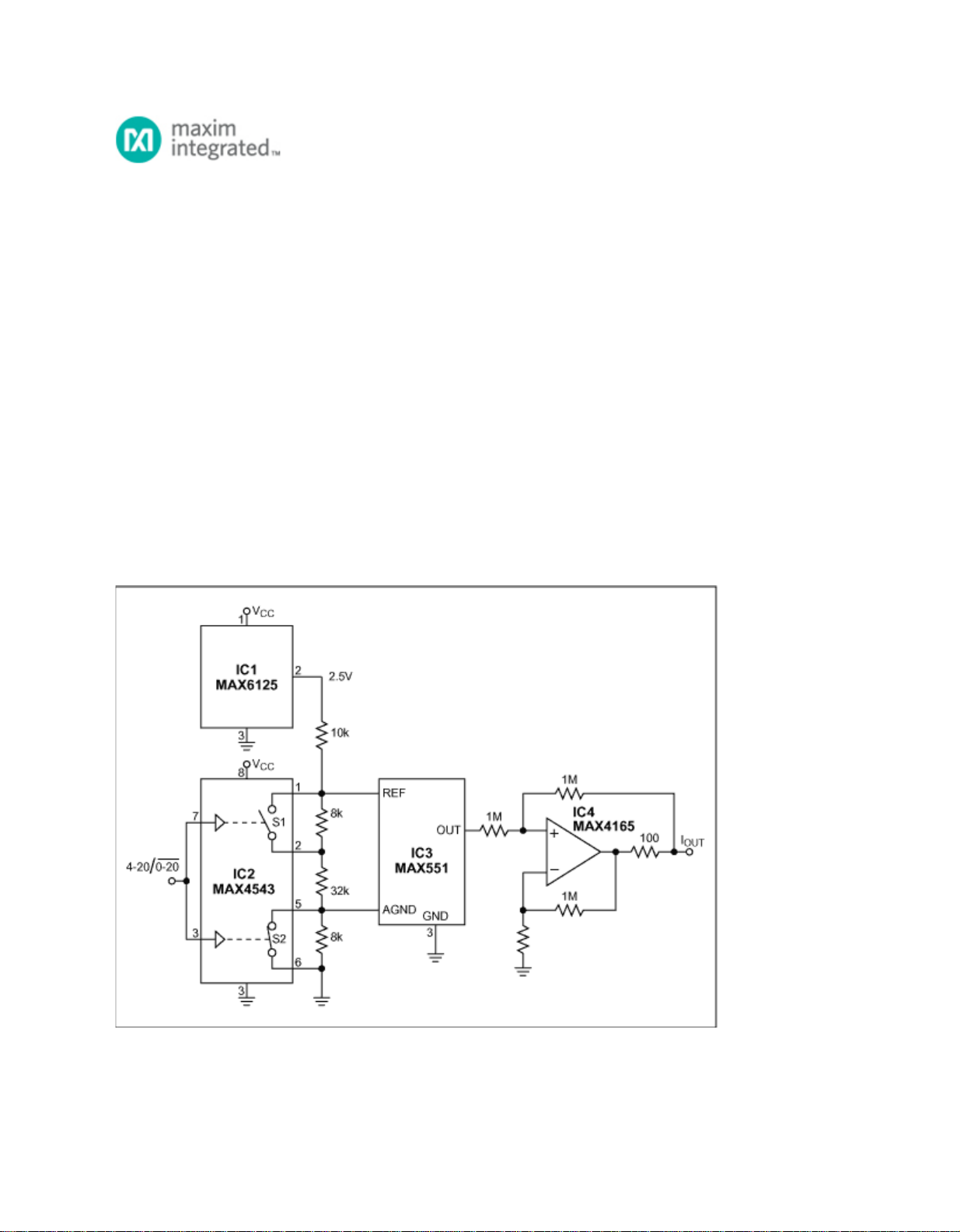
Abstract: This article shows an example of implementing a 4-20mA or 0-20mA current-loop output using
a voltage output digital-to-analog converter (DAC) and a V to I converter.
Current-loop signals, as opposed to voltage signals, are commonly used in industrial systems because
they are much less subject to noise and relatively indifferent to line length (because the current is
unaffected by line resistance). The circuit of Figure 1 allows digital selection between the two standard
ranges of current-loop transmission common in industrial systems (0-20mA and 4-20mA).
Figure 1. This circuit's single control input selects a current-loop range of 0-20mA or 4-20mA.
The analog switch (IC2) controls a resistive divider driven by the 2.5V reference (IC1), such that the
Page 1 of 2