
下载
Keywords:
amplifiers, current-sense amplifiers, over-current protection, high-side current-sense amplifier
APPLICATION NOTE 6329
HOW TO ACCURATELY CALCULATE
OVERCURRENT IN HIGH-SIDE CURRENT-
SENSE AMPLIFIERS
By:
Don Corey, Principal Member of Technical Staff, Maxim Integrated
Abstract: Recently, an engineer asked for a solution to provide high-side monitoring of a 20A load with an
accurate overcurrent detection threshold better than 5%. There are no easily accessible off-the-shelf
solutions that offer the ability to use a low-value sense resistor with less than 5% accuracy! Why 5%?
Would 10% be OK? For a 20A load, a 10% current limit would cause the trip threshold to be 18A
minimum or 22A maximum, a much wider margin than would be acceptable. What are the factors
involved that make 5% so difficult? In this application note, we discuss the challenges of achieving 5%
accuracy, and present a solution that delivers the required accuracy for a high-side current-sense
amplifier over-current protection scheme.
Overview
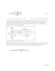
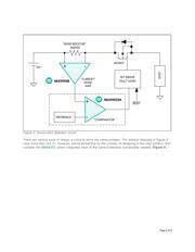
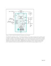
A current-sense amplifier (CSA) can be designed using a variety of topologies, two of which are shown in
Figures 1 and 2. In Figure 1, an operational amplifier (op amp) is configured as a differential amplifier
used to amplify the differential voltage developed across a current-sense shunt resistor. There are some
applications where low-side current-sensing can be used with limitations; however, these cases will not
be discussed in this application note. Refer to Maxim application note 746, "
High-Side Current-Sense
Measurement: Circuits and Principles
" for more details on low-side current-sensing vs. high-side current-
sensing.
The main limitation of the differential amplifier topology is the resistor ratio match of R1 to R4 that sets
the differential gain and the common-mode gain error. Two equations dictate the main source of
accuracy errors for the circuit.
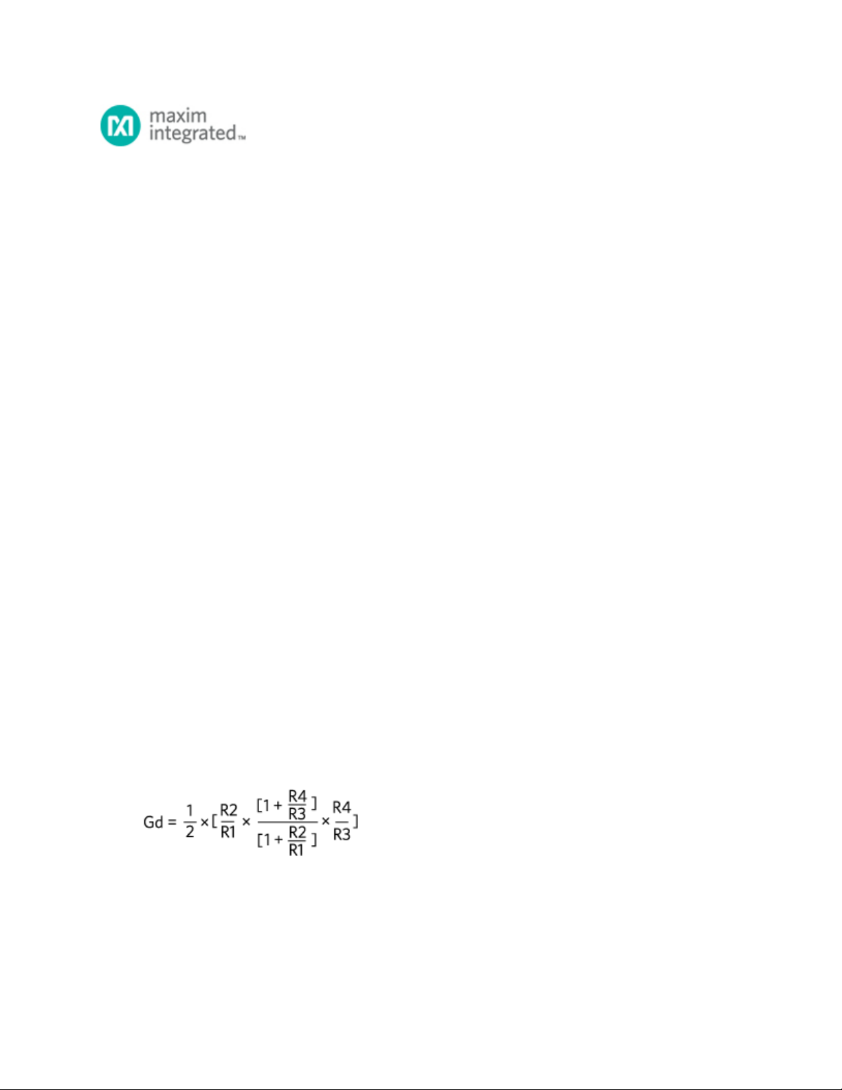
Equation 1 is the equation for the gain of Figure 1 and Equation 2 details
the common-mode gain error.
Equation 3 is used to calculate V for Figure 1.
(Eq. 1)
OUT
Page 1 of 11