


下载

Attend this brief webcast by Maxim on
TechOnline
Maxim > Design Support > Technical Documents > Application Notes > Amplifier and Comparator Circuits > APP 988
Maxim > Design Support > Technical Documents > Application Notes > Audio Circuits > APP 988
Keywords: audio driver, BTL, bridge tied load, PZT, piezoelectric, audio transducer
APPLICATION NOTE 988
Driving Audio Piezoelectric Transducers
Mar 26, 2002
Abstract: This audio application note identifies and describes the key elements in designing a driver for a
piezoelectric transducer (PZT). The relationship between source impedance and sound pressure level is
measured, single-ended (S/E) and bridge-tied load (BTL) driving schemes are compared and the input
impedance of a PZT is characterized.
Audible piezoelectric transducers (PZTs) are often used as warning
devices or alarms. Manufacturers of piezo transducers publish
curves and specifications concerning their respective devices.
However, there are a few important questions that cannot be
answered directly from their data sheets.
What Is the Effect of Source Impedance vs. Sound
Pressure when Driving an Audible PZT?
This has a direct effect on the peak capacity of a power supply that
is used for driving the PZT.
Is There Any Detectable Sound Pressure Difference when Driving an Audible PZT
Single-Ended vs. Bipolar, with the Same Peak-to-Peak Amplitude?
This can impact drive circuit complexity.
What Does the Impedance of a PZT Look Like?
This can affect peak power supply capacity as well as filtering requirements.
Three common PZTs manufactured by Mallory (North American Capacitor Company) were chosen for
investigation of driving source impedance versus sound pressure, single and bipolar drive versus sound
pressure, and PZT impedance characteristics.
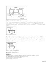
Structure of PZTs
Figure 1 illustrates a cut-away view of a typical audible PZT. A piezoceramic plate is plated with silver
on both sides. One side is bonded to a thin brass plate around the piezoceramic plate's circumference
using an adhesive. This side becomes one electrode connection. The other side of the piezoceramic
plate becomes the second electrode contact. The brass plate is attached to a supporting ring, which is
part of the molded plastic case, using a silicone adhesive.
Page 1 of 12