
下载

Maxim > Design Support > Technical Documents > Application Notes > Interface Circuits > APP 1090
Keywords: RS-485, rs485, EIA/TIA-485, reducing power, cable termination, fail safe, Schottky
termination, low power
APPLICATION NOTE 1090
Methods for Trimming the Power Required in RS-
485 Systems
Mar 01, 2001
Abstract: This paper describes methods of saving power in RS-485 data communication systems.
Methods include low-power transceiver integrated circuits (ICs), ICs with built-in fail-safe thresholds
allowing the elimination of cable fail-safe resistors, use of CMOS rather than TTL drivers, employing the
driver-disable function when not transmitting, eliminating termination resistors in low data rate short
cable length applications, and operation at 3.3V supply when practical. The MAX3088 and MAX3471 are
recommended solutions.
Reducing fat in RS-485 designs that are high in saturated power is simple if you understand how to
maintain good transmission quality at the same time. The following discussion covers the facts, myths,
and dirty tricks you should know to achieve this goal.
Industrial- and building-automation systems include a variety of remote data-acquisition devices that
send and receive data via a central unit that makes the data available to users and other processors.
Data loggers and meter readers are typical of these applications. A near-ideal data-transfer link for this
purpose is defined by the RS-485 standard, which interconnects the data-acquisition devices with a
single twisted-pair cable.
Because many of the data-acquisition and data-collection devices in an RS-485 network are small,
handheld, battery-powered gadgets, power conservation is necessary for controlling their heat buildup
and extending battery life. Similarly, power consumption is an issue for handheld instruments and other
applications that use the RS-485 interface for downloading data to a host processor.
If you are not familiar with RS-485, please also see RS-485 Basics.
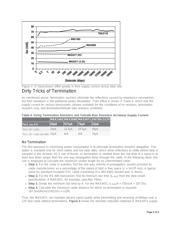
Where Does All the Power Go?
An obvious indicator of power loss is the transceiver's quiescent current (I
Q
), and modern parts reduce
this factor dramatically. Table 1 compares the quiescent current of low-power CMOS transceivers with
the bipolar, industry-standard 75176.
Table 1. Quiescent Current Comparison for Various RS-485 Transceivers
Part
I
Q
(Driver
Disabled)
I
Q
(Driver
Enabled)
Shutdown
Current
Maximum Data
Rate
MAX3471 2.8µA 83µA N/A 64kbps
MAX1483 20µA 55µA 0.1µA 250kbps
Page 1 of 9