


下载

Maxim > Design Support > Technical Documents > Application Notes > Interface Circuits > APP 5151
Maxim > Design Support > Technical Documents > Application Notes > Sensors > APP 5151
Keywords: IO-Link, wake-up, transceiver, sensor, industrial sensor, industrial actuator
APPLICATION NOTE 5151
Special Considerations for Mode Changes During
Active Operation of MAX14820/MAX14821
Sensor/Actuator Transceivers
By: Shasta Thomas, Applications Engineer
Oct 20, 2011
Abstract: The MAX14820/MAX14821 are Maxim's first sensor/actuator transceivers designed for IO-
Link® device applications. Both transceivers have an on-board C/Q driver that can be adjusted via the
SPI™ interface during active operation. However, there are some special considerations that must be
taken into account to avoid falsely detecting a wake-up event. This application note discusses those
considerations.
The IO-Link Wake-Up Protocol
In an IO-Link system, communication between a master and a device is point-to-point, with the master
sending a request message and the device responding to it. During startup, the IO-Link master initiates
a special wake-up current pulse that lasts from 30µs to 160µs to initiate communication with the device,
while auto-adjusting the data transmission rate and checking the device identification.
The MAX14820/MAX14821 are Maxim's first sensor/actuator transceivers designed for IO-Link device
applications. In these applications, the MAX14820/MAX14821 act as the physical layer interface to a
microcontroller running the data-link layer protocol. The transceivers detect IO-Link wake-up requests
from an IO-Link master on the C/Q line and, in turn, generate a wake-up signal to the microcontroller
using the active-low wake-up output pin (/WU\) output.
Normal Wake-Up Detection
The MAX14820/MAX14821 can detect a wake-up request from an I/O Link master when the C/Q line is
shorted for 80µs (typ) in any of the programmable output modes (push-pull, PNP, or NPN). The /WU\
output pulses low for 190µs (typ) when a valid wake-up pulse is detected on the C/Q line, signaling to
the microcontroller that a wake-up request has been received. Wake-up detection is functional as long
as the C/Q driver is enabled.
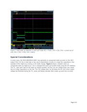
Figure 1 shows normal wake-up functionality with C/Q in push-pull mode. The master holds the C/Q
line during a TX_ pulse, triggering a wake-up pulse on the MAX14820/MAX14821. As shown here, the
devices generate a pulse on the /WU\ output when a wake-up event is detected.
Page 1 of 5