
下载
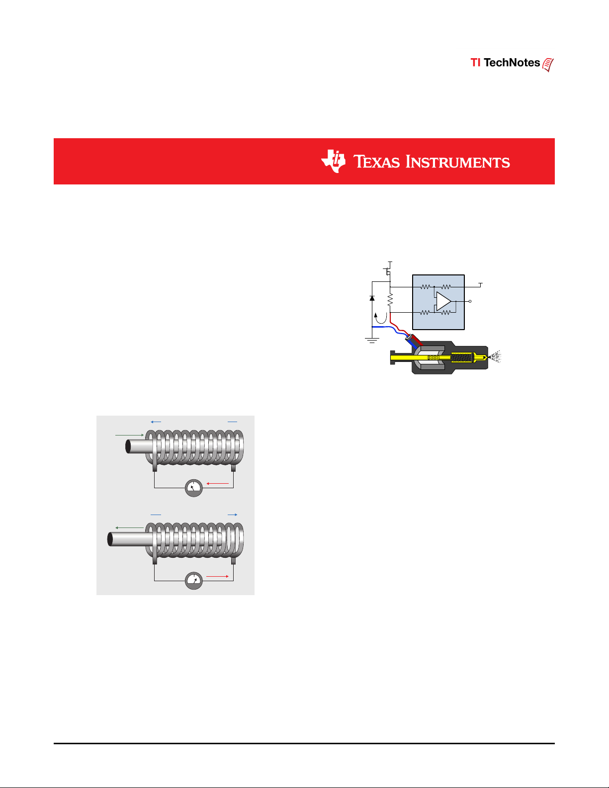
Induced Magnetic Field Inside Coil
Induced Magnetic Field Inside Coil
Rod Moves In
Rod Moves Out
Current
Current
S
S
N
N
-
+
INA240
Battery
Reference
Voltage
1
SBOA166A–October 2016–Revised December 2016
Submit Documentation Feedback
Copyright © 2016, Texas Instruments Incorporated
High-Side Drive, High-Side Solenoid Monitor With PWM Rejection
Arjun Prakash,
Current Sensing Products
____________________________________________________
High-Side Drive, High-Side Solenoid Monitor With PWM
Rejection
Arjun Prakash, Current Sensing Products
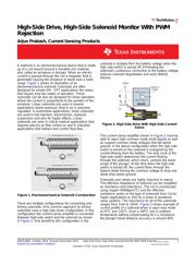
A solenoid is an electromechanical device that is made
up of a coil wound around a movable iron material,
also called an armature or plunger. When an electric
current is passed through the coil a magnetic field is
generated causing the armature to travel over a fixed
range. Figure 1 shows an illustration of an
electromechanical solenoid. Solenoids are often
designed for simple ON - OFF applications like relays
that require only two states of operation. These
solenoids can be also be designed for linear operation
where the current is proportional to the position of the
armature. Linear solenoids are used in several
applications where pressure, fluid or air is precisely
regulated. In automotive applications, linear solenoids
are used in fuel injectors, transmission, hydraulic
suspension and also for haptic effects. Linear
solenoids are seen in critical medical applications that
requires precise air flow control as well in industrial
applications that redirect and control fluid flow.
Figure 1. Electromechanical Solenoid Construction
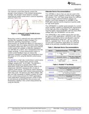
There are multiple configurations for connecting and
driving solenoids. One common approach to driving
solenoids uses a high-side driver configuration. In this
configuration the current sense amplifier is connected
between high-side switch and the solenoid as shown
in Figure 2. One benefit to this configuration is the
solenoid is isolated from the battery voltage when the
high side switch is turned off. Eliminating the
solenoid's continuous connection to the battery voltage
reduces solenoid degradation and early lifetime
failures.
Figure 2. High-Side Drive With High-Side Current
Sense
The current sense amplifier shown in Figure 2 must be
able to reject high common mode dv/dt signals as well
as support common mode voltages that fall below
ground. In the above configuration when the high side
switch is turned on the solenoid is energized by the
current flowing from the battery. The duty cycle of the
high-side switch determines the current flowing
through the solenoid, which inturn, controls the travel
range of the plunger. At the time when the high-side
switch is turned off, the current flows through the
flyback diode forcing the common voltage to drop one
diode drop below ground.
Solenoids and valves are highly inductive in nature.
The effective impedance of solenoid can be simplified
as resistance and inductance. The coil is constructed
using copper (4000ppm/°C) and the effective
resistance varies on the type of solenoids from 1Ω for
haptic applications to 10Ω for a linear or positional
valve systems. The inductance for all of the solenoids
ranges from 1mH to 10mH. Figure 3 shows example of
current profile of a solenoid driver in open loop mode
at 25°C and 125°C. Over a 100°C rise in ambient
temperature without compensating for Cu resistance
the plunger travel distance accuracy is around 40%.